Borehole Source of SH and P Waves SHock
Borehole Source of SH and P-Waves SHock
Main features:
- P and SH wave generation
- Suitable for CST and VSP
- High frequency repeatable signal
- Operations in dry and water-filled wells
- HV slip ring on the winch
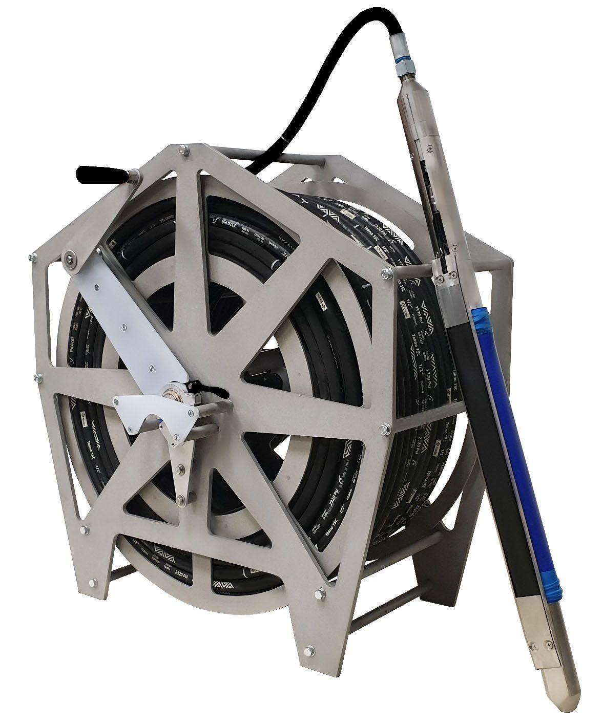
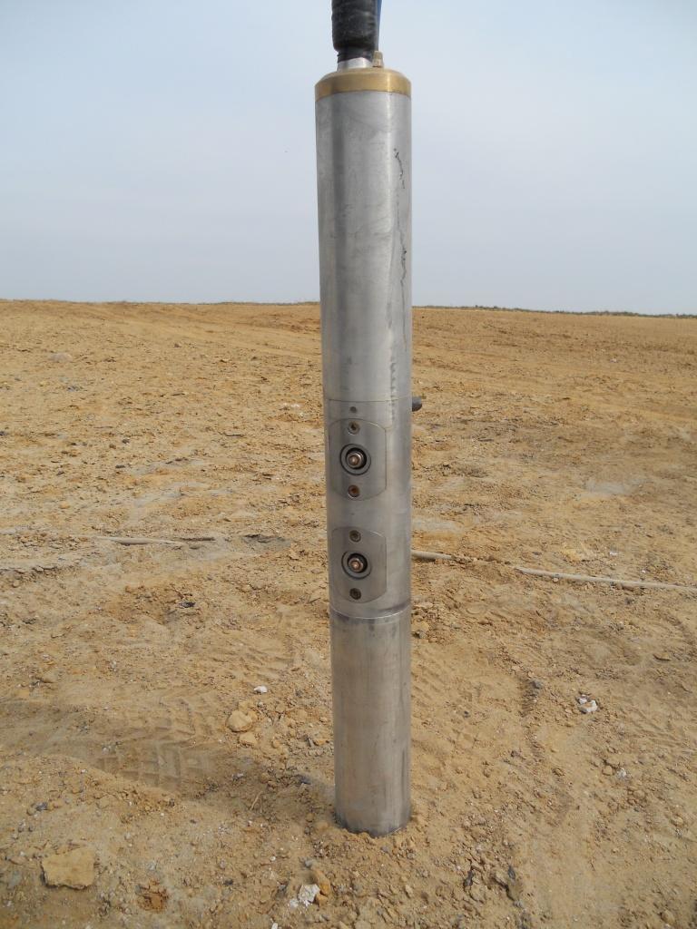
SHock is a unique borehole source, which is designed for generating horizontally polarised Shear Waves (SH) and Compressional Waves (P) for reversed Vertical Seismic Profiling (VSP) and Crosshole Seismic Testing or Tomography (CST). SHock is an easy-to-operate high-repeatable seismic source, which can be used both in dry and water-filled wells in combination with energy source Jack.
A rigid pneumo-electric line provides accurate source rotation in the well for generating shots with opposite SH-wave polarization for further signal-to-noise ratio enhancement during the processing and possibility to clearly identify S-waves by reversed polarity. Due to its electrodynamical nature, SHock generates high frequency energy pulse, which results in high resolution seismic gathers suitable for very accurate first break picking and providing very detailed VSP seismic sections.
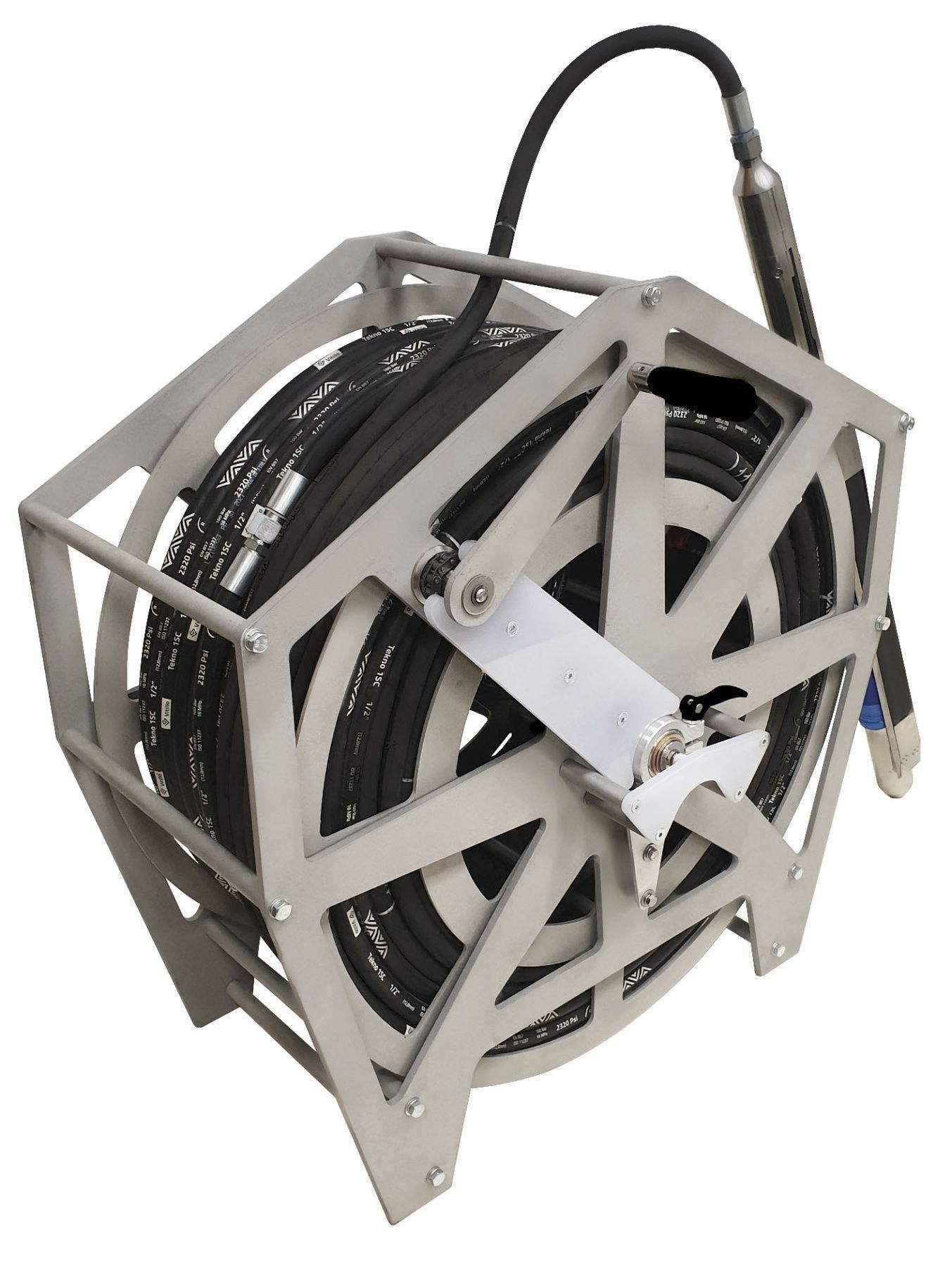
To provide fast infield seismic borehole acquisition, SHock source is supplied on a reel with a high-voltage slip ring and pneumatic fitting. It allows to acquire seismic data without need of disconnecting the energy source and compressor during winding the cable.
SHock standard set includes:
- SHock source
- Pneumo-electric line
- Reel with high-voltage slip ring
- Reel and energy source connection wire
- Air compressor (option)
To perform CST on P and S waves following equipment is required:1. Energy source Jack2. GStreamer with the seismograph (DAQlink 4)3. RadExPro for data processing and ZondST2d/ZondST3d for tomography inversion.
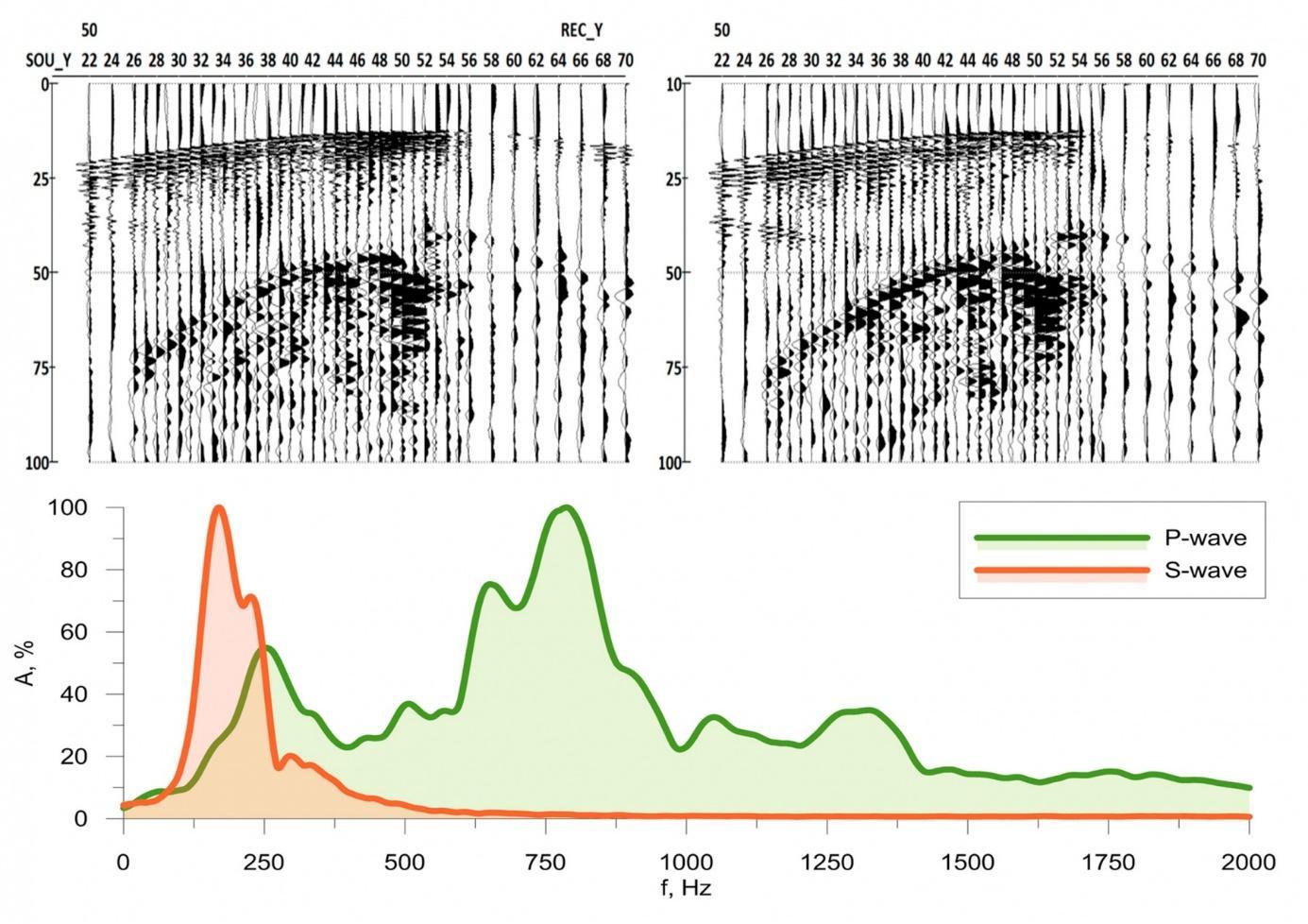 Common receiver gather, acquired by SHock borehole seismic source and three-component (3C) geophones, located in the nearby well.
Two gathers are shown on the top, P and S waves spectra are shown on the bottom. Source operation was provided by energy source Jack.Sedimentary rocks, approximately 30 meters between wells, the source is located at a depth of 50 meters, data collected by GStreamer with receiver depths from 22 to 70 meters.
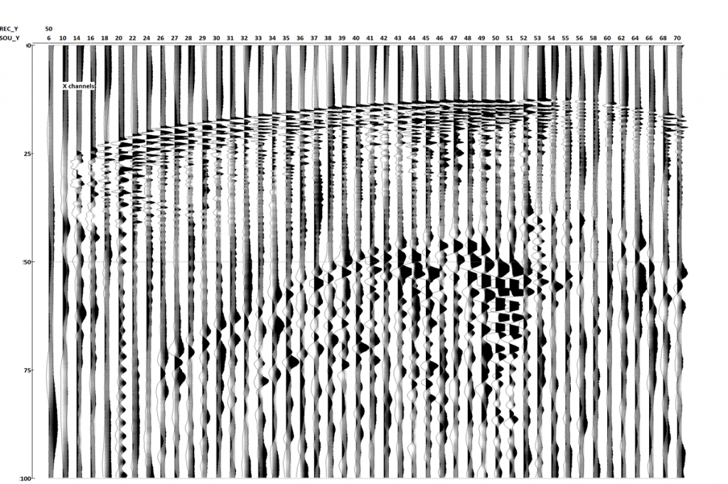
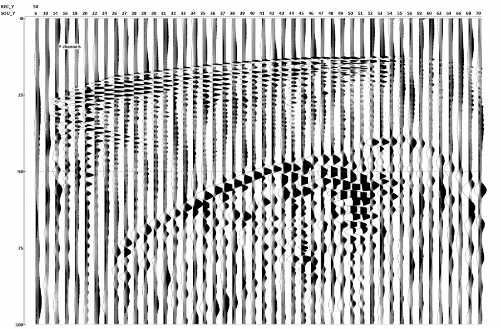 Common receiver gather with non-oriented X and Y components. Shots with opposite polarity are overlaid on each trace.
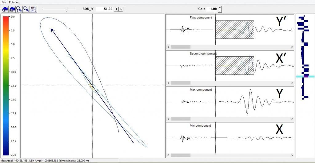 Orientation of horizontal components (Uy, Ux) using RadExPro seismic software.
The hodogram on the left represents particle motion trajectory of the earth of two horizontal components for the selected part of the first breaks. Unrotated traces in acquisition coordinates (Y’, X’) and rotated traces (Y’, X’) in radial-transverse coordinates are shown on the right. This procedure is a standard VSP processing routine and allows to use 3C receivers without any additional components or compasses that take up extra space in the probe, making it more expensive and heavier.
 Example of data after 3C records orientation and subtraction of "right" and "left" blows
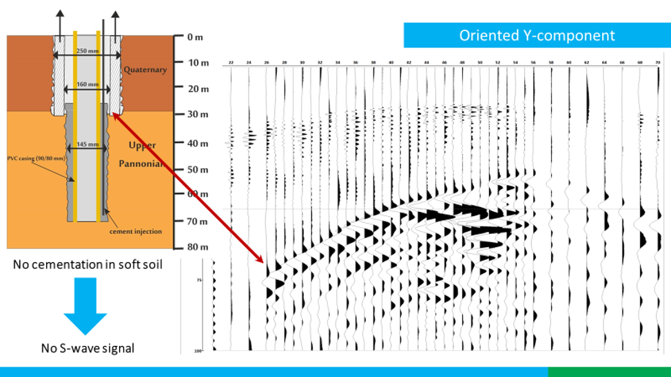 CST survey on P and S waves requires preparing wells in accordance with ASTM D4428/D4428M, i.e. working in an open borehole or cementing the annular space in case PVC well casing is used.

